Subscribe For Free Updates!

We'll not spam mate! We promise.

Friday 18 April 2014

Introduction to TCP/IP Layers

TCP/IP Layers

Introduction 
Computer communication follows some well defined rules and guidelines which we call protocols. In order for the computers to exchange data they have to agree on using the same rules, otherwise they become incompatible. That was the case in the past. This was one of the reasons to create a common model for communication. It was called OSI Model (Open Systems Interconnection). This was an attempt to make different vendor's computers exchange data easily. This way IBM machines could talk to DEC machines and so on. Today however, it is the TCP/IP model that is all-pervasive. This protocol suite is derived from OSI model and somewhat loosely follows its rules and terminology. This is going to be the focus of our discussion and the main topic of this lesson.

Note!
Remember that TCP/IP model does not follow OSI model exactly. OSI model is now used as a reference. What's described in this blog is TCP/IP model, not OSI or IPX/SPX model. Look at the comparison below:

TCP/IP Layers
The designers decided to break down the whole complexity of data exchange and created five layers of functions to accomplish the goal. This approach helps develop and modify certain layers of code without touching other layers. For instance, if you are an application programmer, you will be writing a code in the 'application layer' which allows you to use already written code dealing with the transport of data between computers. You do not even have to learn how this transport is done. It has already been written for you. This way, you focus on the application you're creating, what it does and how it works rather than learning about network adapter drivers, signaling and other gory, hardware details.

TCP/IP model divides the functions related to data transmission by using five distinct layers of responsibility. Below area these layers.


Layer 5-7 - Application
This is where the data's journey begins. Everyday, you use many applications that  rely on network services. Those applications are classified to be layer 5 code. Your web browser and web server, mail client and mail server, ssh client and ssh server etc. You may have noticed the term client andserver often used in the above description. Pretty much all applications use this architecture.Client, is an application that requests some services from the server application. Server application is providing a client with what they want. A common example of that architecture is your Firefox orInternet Explorer web browser (client application) requesting a page from Apache or IIS web server (server application). Applications, in general, provide a User Interface (UI) which offloads us from a burden of knowing how a computer does things internally.

So, once your application formed the request, that one is sent down to the layer 4 (transport layer) asking for the delivery to the host somewhere in the network.

Layer 4 - Transport
This layer accepts all requests coming from the upper layer (application layer) and tries to organize the transport of that request across the network. In TCP/IP model this layer of software is responsible for:

  • Breaking down big files that are sent across into smaller chunks called segments. There are technology limitations that do not allow our computers to send large files in one piece. It would not be a good idea anyway as any small change of the data during transmission would make the sender re-transmit the whole file again instead of the smaller chunk only. That of course, would take more time and resources to successfully transmit the data.
  • As your computer uses many applications that will transmit something across the network at the same time, the system must know how to mark those request such that they are delivered to the right receiver applications. And once the replies are coming back, they should be delivered back to the same process that initiated them. The concept of the port number has been introduced to deal with that. Source and destination ports ensure that all requests and replies are delivered to the appropriate processes on the computers exchanging data. More on that later in the upcoming lessons.
  • This layer also allows the application to use connection-oriented or connectionlessservices. The former, establishes communication with the receiving computer (or more generally: destination host) before data can be exchanged, the latter will send data without ensuring that the destination application is running and willing to receive anything. This form of transmission is used primarily for voice and video applications.
  • This layer will also give applications some options in terms of the reliability. Depending on which layer 4 protocol the application is designed to use, the reception of data can be verified or not. That creates reliable versus unreliable transport respectively. In the reliable transport any data that has not been delivered will be retransmitted, unlikely the unreliable transport.
  • One other function of layer 4 could be to moderate the transmissions so that the receiving host is neither swamped by the excess of packets coming in nor is it waiting and doing nothing because the sender's speed of transmission is too slow. Majority of the functions above are performed by TCP protocol, not UDP as applications choose one of them to use.
Once all aspects and functions in this layer have been taken care of, layer 4 sends the data it received from layer 5 down to the layer 3 requesting its service.

Layer 3 - Internet
Upon receiving a request from layer 4, this code is going to process the incoming information. Since, typically we have more than one path between the sender (source) and the receiver (destination), the function of this layer is to find the best path between them. In order to accomplish that there are two concepts I need to introduce here.

Firstly, we need to know how computers find themselves in the network. This is accomplished by using specially designed, layer 3 addresses uniquely identifying computers in any network. The addresses used by this layer consist of four bytes delimited by the dots (e.g. 10.1.1.1) which are followed by a, so called, 'netmask' also consisting of four bytes with the dot used as the delimiter (e.g. 255.255.255.0). The whole IP address can look like this:
10.1.1.1 255.255.255.0. More on those later.

Secondly, because the destination of our data can be outside of our own network, a device calledrouter has been introduced to find the optimal paths between the different networks in which the computers reside. The data processed by layer 3 is called a packet or datagram. This layer also uses a mapping to the upper layer 4 that has requested its services. This is due to the fact that there are more than one protocols available in layer 4 (TCP or UDP). This information (which layer 4 protocol is sending the data) is going to be useful when the data arrives at the destination and the destination's layer 3 process needs to send the content to the appropriate layer 4 protocol for processing. It has to be the SAME protocol that the sender used in layer 4.


Layer 2 - Network Interface (Data Link in OSI model)
There is a great variety of technologies that handle data transmission on media such as copper and fiber optics cables or air (wireless). In order to offload the layer 3 protocols from learning all possible signaling methods, layer 2 was created. Thus, layer 3 can focus on finding the best path between the source and the destination, and the layer 2 functions will handle the details of preparing the data to be placed on the actual media (copper wire, fiber, air etc.). The piece of information processed at this layer is called a frame. This layer will also use specially designed addressing scheme to recognize the next device which a computer is sending the data to. For instance, in the commonly used layer 2 technology called Ethernet, this address uniquely identifying hosts in the same network is called MAC Address. The reason why we use different addressing schemes: layer 3 and layer 2, will become clearer when we get into some details of the actual data exchange. Please, bear with me till we reach the right lesson that explains it in more detail. The device that is capable of understanding the structure of a frame and delivers the data between the hosts in the SAME network is called bridge, or switch. As of the time of writing this, switches are very popular devices and bridges can be found mostly in museums.

Once the layer 2 has prepared the data which layer 3 requested to send, (the process is called 'framing'), layer 2 will send the request to layer 1 asking for the data to be placed onto the wire/fiber/air using the appropriate signaling method.

Layer 1 - Network Interface (Physical Layer in OSI)
This layer receives requests from layer 2 (data traveled from layer 5 to layer 1 now). The physical layer is going to encode data received from layer 2 software and place them in the form of bits (1s and 0s) on the medium. This way, ones and zeros travel across the media to deliver them to their receipient. The bits can traverse multiple devices as they go across such as hubs, switches, routers. What type of devices will forward those bits depends on the design of the network. The devices referred to as layer 1 devices are hubscablesnetwork adaptersconnectors,transceivers etc. Also the data processed by this layer is called bits. This layer defines low level aspects of the transmission such as cables used, maximum distance the cable can reliably sent bits across, types of the connectors, speed of the transmissions etc.

Firewall Security-Level

Firewall Security-Level


This is my first Security Post regarding Cisco PIX/ASA firewalls. To begin with, what is a firewall? Literally, in the real world, a firewall as part of a building, is used to you guessed it: protect the building from fire. :) The same applies in the networking world. A firewall is a device that prevents unauthorized access and permits authorized access to a network. A firewall may function for packet filtering, proxy server and stateful packet filtering. Cisco PIX/ASA devices function as stateful packet filtering devices, which builds a stateful connection table to verify the connections.

A firewall prevents access from the untrusted network to the trusted network. An interface of the firewall may belong to the untrusted or the trusted. The interface that belongs to the trusted network is often called the inside interface and the untrusted one is the outside interface. Security-levels from 0-100 indicates the level of trust for an interface. The higher the number the more trusted the interface. The rule in security-level is that a higher security level can have access to a lower security level, the lower security level doesn't have access to a higher security level and is blocked by default. Interfaces with the same security levels are blocked as well.

Let's configure interfaces and lets see how security-levels are applied automatically and manually. I am using a PIX firewall.

First lets configure an outside interface.


petesfirewall(config)# interface ethernet0
petesfirewall(config-if)# nameif outside
INFO: Security level for "outside" set to 0 by default.

The "nameif" command is basically used to name an interface. Very obvious isn't it?:) Notice that once we named the interface "outside", Cisco automatically set the security-level to 0 meaning its untrusted. Next we configure an inside interface.


petesfirewall(config-if)# interface ethernet1
petesfirewall(config-if)# nameif inside
INFO: Security level for "inside" set to 100 by default.

The PIX now configures the security level by 100 which means its a trusted interface. For this reason, traffic from ethernet1 to ethernet0 is permitted by default but traffic from ethernet0 to ethernet1 is not. This is where inbound access-list comes in to allow traffic from an untrusted interface to a trusted one.

Let us now configure an interface named "webservers". You can use any name you like by the way. Let's give it a security-level of 60.


petesfirewall(config-if)# interface ethernet2 
petesfirewall(config-if)# nameif webservers
INFO: Security level for "webservers" set to 0 by default.
petesfirewall(config-if)# security-level 60

Notice that any interface name other than "inside" is automatically given a 0 security-level value. The "security-level" command is used to specify manually a security level to an interface. Ethernet2 by default can access Ethernet0 but can't access Ethernet1, because the latter has a higher security-level than the former. The "show nameif" command is a very useful command to display the names of the interfaces including the security-levels.


petesfirewall(config)# show nameif 
Interface                Name                     Security
Ethernet0                outside                    0
Ethernet1                inside                   100
Ethernet2                webservers                60

As you can see, in the PIX firewall the show command is accepted unlike in the routers which doesn't accept show commands in the global-configuration mode. For those have been configuring routers, adapting to configuring firewalls would be easy. After all, its still Cisco. :)

Finally, sometimes there is a need to allow access to interfaces with the same security-level. The command below, will allow such access.


petesfirewall(config)# same-security-traffic permit inter-interface

There you have it. Its easy as one, two, three. Good day homies!

Router as a DNS server

Cisco Router as a DNS server


Not exactly like a DNS server that is hosted from a server and so on and so forth, the Cisco Router can act like a DNS server without the service stated above. It can even act as a proxy dns server, meaning forwarding the request to the upstream DNS server and cache the replies from the DNS server, so it can use the cache entries for other requesting hosts. We will only focus on the simple and practical configuration. I don't even know if this feature can be called a "DNS server" feature. :P If you have your own Dynamips Lab and has fixed ip addresses, it would be easier though to use hostnames when trying to ping devices. This can be achieved by the "ip host" command. It can be configured as the example below.


Router(config)#ip host R1 1.1.1.1
Router(config)#ip host R2 2.2.2.2
Router(config)#ip host R3 3.3.3.3
Router(config)#ip host R4 4.4.4.4

Let's do a ping test.


Router#ping R1

Type escape sequence to abort.
Sending 5, 100-byte ICMP Echos to 1.1.1.1, timeout is 2 seconds:
...

Well, R1 now resolves to 1.1.1.1. There you have it, makes life easier !

VRF Route Target

VRF Route Target


MPLS VPN implementation requires VRF and also exporting and importing routes for that VRF. I mentioned on my previous posts about VRF that the VRF name is locally significant and even the RD number. What counts is what you import and export. Importing and exporting route targets use the same syntax as the RD and it is ASN:NN as shown by the example below.


!
ip vrf ALL-VRF
rd 123:4
route-target export 123:4
route-target import 123:1
route-target import 123:2
route-target import 123:3

By definition the routes that you "export" are only the routes you advertise on the vrf address family in BGP. The routes that you import are the cummulative routes with the same label that were exported from the other routers participating in the MPLS VPN. Remember that you don't export what you have learned through importation. Check the diagram below and the scenario we need to accomplish in this lab.


Scenario Conditions:

1. EMEA should have full ip reachability to APAC and AMERICAS but APAC and AMERICAS should not see each other.
2. RR should only see the all the routes but will not be seen by the routers.

I have setup everything and configured MPLS as well. I have configured the clients on the RR on both ipv4 and vpnv4 address-families. The command "show ip bgp vpnv4 all sum" on the RR should show that its learning prefixes from the clients.

RR#sh ip bgp vpnv4 all sum
BGP router identifier 123.123.123.4, local AS number 123
BGP table version is 13, main routing table version 13
12 network entries using 1644 bytes of memory
12 path entries using 816 bytes of memory
4/3 BGP path/bestpath attribute entries using 496 bytes of memory
3 BGP extended community entries using 72 bytes of memory
0 BGP route-map cache entries using 0 bytes of memory
0 BGP filter-list cache entries using 0 bytes of memory
BGP using 3028 total bytes of memory
BGP activity 12/0 prefixes, 12/0 paths, scan interval 15 secs

Neighbor        V    AS MsgRcvd MsgSent   TblVer  InQ OutQ Up/Down  State/PfxRcd
123.123.123.1   4   123      52      57       13    0    0 00:40:41        2
123.123.123.2   4   123      53      61       13    0    0 00:41:26        2
123.123.123.3   4   123      43      44       13    0    0 00:36:44        2

We can clearly see that its learning prefixes in the vpnv4 but will not put those routes in the routing table until it has been imported in one of the VRF's. In our case, I have configured vrf ALL-VRF in RR and imported all the route-targets 123:1, 123:2 and 123:4. In a VRF you can export and import as many route-targets as needed. Lets see if RR can see the routes now

RR

!
ip vrf ALL-VRF
rd 123:4
route-target export 123:4
route-target import 123:1
route-target import 123:2
route-target import 123:3

RR#sh ip route vrf ALL-VRF

Routing Table: ALL-VRF
Codes: C - connected, S - static, R - RIP, M - mobile, B - BGP
   D - EIGRP, EX - EIGRP external, O - OSPF, IA - OSPF inter area
   N1 - OSPF NSSA external type 1, N2 - OSPF NSSA external type 2
   E1 - OSPF external type 1, E2 - OSPF external type 2
   i - IS-IS, su - IS-IS summary, L1 - IS-IS level-1, L2 - IS-IS level-2
   ia - IS-IS inter area, * - candidate default, U - per-user static route
   o - ODR, P - periodic downloaded static route

Gateway of last resort is not set

 1.0.0.0/32 is subnetted, 1 subnets
B       1.1.1.1 [200/0] via 123.123.123.1, 00:46:26
 2.0.0.0/32 is subnetted, 1 subnets
B       2.2.2.2 [200/0] via 123.123.123.2, 00:46:26
 33.0.0.0/32 is subnetted, 1 subnets
B       33.33.33.33 [200/0] via 123.123.123.3, 00:46:26
 3.0.0.0/32 is subnetted, 1 subnets
B       3.3.3.3 [200/0] via 123.123.123.3, 00:46:26
 22.0.0.0/32 is subnetted, 1 subnets
B       22.22.22.22 [200/0] via 123.123.123.2, 00:46:26
 11.0.0.0/32 is subnetted, 1 subnets
B       11.11.11.11 [200/0] via 123.123.123.1, 00:46:28
 123.0.0.0/32 is subnetted, 1 subnets
C       123.123.123.14 is directly connected, Loopback40

Ok, we have meet the first condition. RR is now able to see the routes exported by the RR clients. They won't see the route advertised in RR because the clients are not even importing that route. Full reachability in MPLS VPN requires that one router's exported route-target should be imported by another and vice-versa, otherwise you can only see the route but you won't be able to reach it. The networks should be in the corresponding VRF routing table of the routers.

To illustrate this point, let's configure the second scenario. Below are the VRF configurations on the 3 clients.

APAC#

!
ip vrf APAC
rd 123:1
route-target export 123:1
route-target import 123:3

AMERICAS#

!
ip vrf AMERICAS
rd 123:2
route-target export 123:2
route-target import 123:2

EMEA#
!
ip vrf EMEA
rd 123:3
route-target export 123:3
route-target export 123:2
route-target import 123:1
route-target import 123:2

APAC is exporting route-target 123:1 and its importing 123:3 which is exported by EMEA. EMEA on the other hand is importing 123:1 and exporting 123:3. There should be full ip reachability between the two. By the way the route-target ID doesn't necessarily match with the RD. Normally for networks that should see each other in MPLS VPN both the export and import route target ID's are the same. It will get rid of any unnecessary confusion created by using different RT ID's. Take into consideration AMERICAS and EMEA routers. As you can see on the config above, AMERICAS is importing and exporting 123:2. One command can generate the both export and import and that is "route-target both 123:2". EMEA is importing and exporting also 123:2 which means they will reach each other. Let's test if we have accomplished the condition, we will show the routing table in APAC and AMERICAS and let's ping the networks in EMEA. The ping should be sourced on the loopback interfaces where we configured the VRF's.

APAC#sh ip route vrf APAC

Routing Table: APAC
Codes: C - connected, S - static, R - RIP, M - mobile, B - BGP
   D - EIGRP, EX - EIGRP external, O - OSPF, IA - OSPF inter area
   N1 - OSPF NSSA external type 1, N2 - OSPF NSSA external type 2
   E1 - OSPF external type 1, E2 - OSPF external type 2
   i - IS-IS, su - IS-IS summary, L1 - IS-IS level-1, L2 - IS-IS level-2
   ia - IS-IS inter area, * - candidate default, U - per-user static route
   o - ODR, P - periodic downloaded static route

Gateway of last resort is not set

 1.0.0.0/32 is subnetted, 1 subnets
C       1.1.1.1 is directly connected, Loopback0
 33.0.0.0/32 is subnetted, 1 subnets
B       33.33.33.33 [200/0] via 123.123.123.3, 01:04:51
 3.0.0.0/32 is subnetted, 1 subnets
B       3.3.3.3 [200/0] via 123.123.123.3, 01:04:51
 11.0.0.0/32 is subnetted, 1 subnets
C       11.11.11.11 is directly connected, Loopback10

APAC#ping vrf APAC 3.3.3.3 source lo0


Type escape sequence to abort.
Sending 5, 100-byte ICMP Echos to 3.3.3.3, timeout is 2 seconds:
Packet sent with a source address of 1.1.1.1
!!!!!
Success rate is 100 percent (5/5), round-trip min/avg/max = 248/346/436 ms


AMERICAS#sh ip route vrf AMERICAS

Routing Table: AMERICAS
Codes: C - connected, S - static, R - RIP, M - mobile, B - BGP
   D - EIGRP, EX - EIGRP external, O - OSPF, IA - OSPF inter area
   N1 - OSPF NSSA external type 1, N2 - OSPF NSSA external type 2
   E1 - OSPF external type 1, E2 - OSPF external type 2
   i - IS-IS, su - IS-IS summary, L1 - IS-IS level-1, L2 - IS-IS level-2
   ia - IS-IS inter area, * - candidate default, U - per-user static route
   o - ODR, P - periodic downloaded static route

Gateway of last resort is not set

 2.0.0.0/32 is subnetted, 1 subnets
C       2.2.2.2 is directly connected, Loopback0
 33.0.0.0/32 is subnetted, 1 subnets
B       33.33.33.33 [200/0] via 123.123.123.3, 00:56:20
 3.0.0.0/32 is subnetted, 1 subnets
B       3.3.3.3 [200/0] via 123.123.123.3, 00:56:20
 22.0.0.0/32 is subnetted, 1 subnets
C       22.22.22.22 is directly connected, Loopback10

AMERICAS#ping vrf AMERICAS 3.3.3.3 source lo0

Type escape sequence to abort.
Sending 5, 100-byte ICMP Echos to 3.3.3.3, timeout is 2 seconds:
Packet sent with a source address of 2.2.2.2
!!!!!
Success rate is 100 percent (5/5), round-trip min/avg/max = 184/593/1020 ms


EMEA#sh ip route vrf EMEA

Routing Table: EMEA
Codes: C - connected, S - static, R - RIP, M - mobile, B - BGP
   D - EIGRP, EX - EIGRP external, O - OSPF, IA - OSPF inter area
   N1 - OSPF NSSA external type 1, N2 - OSPF NSSA external type 2
   E1 - OSPF external type 1, E2 - OSPF external type 2
   i - IS-IS, su - IS-IS summary, L1 - IS-IS level-1, L2 - IS-IS level-2
   ia - IS-IS inter area, * - candidate default, U - per-user static route
   o - ODR, P - periodic downloaded static route

Gateway of last resort is not set

 1.0.0.0/32 is subnetted, 1 subnets
B       1.1.1.1 [200/0] via 123.123.123.1, 00:00:00
 2.0.0.0/32 is subnetted, 1 subnets
B       2.2.2.2 [200/0] via 123.123.123.2, 01:07:06
 33.0.0.0/32 is subnetted, 1 subnets
C       33.33.33.33 is directly connected, Loopback10
 3.0.0.0/32 is subnetted, 1 subnets
C       3.3.3.3 is directly connected, Loopback0
 22.0.0.0/32 is subnetted, 1 subnets
B       22.22.22.22 [200/0] via 123.123.123.2, 01:07:06
 11.0.0.0/32 is subnetted, 1 subnets
B       11.11.11.11 [200/0] via 123.123.123.1, 00:00:03

It will take a while to get used to VRF Route-target if you are just learning it but this should be pretty easy. Remember, you can't reach a network that you have imported unless it exported your network. In MPLS VRF, entries in your VRF routing table doesn't assure reachability, the router in the destination network should also have your network in its VRF routing table. Ok, we are done !

IPSEC VPN Configuration

 IPSEC VPN Configuration


IPSEC VPN's have revolutionized the networking world. It is usually used over the unsecured network called "the Internet". It's a way to ensure secure transfer of data over the internet and used for site to site connections and telecommuters who need remote access from anywhere to the corporate Intranet or for remote branch offices that only have internet connection. We have a basic diagram below and lets configure a Site to Site IPSEC VPN. We will focus more on configuration not on the nitty gritty details of the protocols and the process of VPN creation.


Let's pretend ISP is the Internet Cloud. We have R1 and R2 connected through an internet leased line to their ISP's. Lets say R2 has a server 2.2.2.2 which R1 needs to access from 1.1.1.1 in its network. (1.1.1.1 and 2.2.2.2 are just loopback addresses in R1 and R2 respectively) We will build a VPN tunnel allowing 1.1.1.1 to access 2.2.2.2 and vice versa. Steps are numbered but not necessarily the standard way but a more favorable way of configuring.


1. Create an access-list on both R1 and R2. This will indicate the "interesting traffic". This means that anything that matches the ACL applied to the tunnel configuration will pass through the tunnel instead of exiting the interface facing the internet.

R1(config)#access-list 100 permit ip host 1.1.1.1 host 2.2.2.2
R2(config)#access-list 100 permit ip host 2.2.2.2 host 1.1.1.1

Notice that the ACL's mirror each other.

2. Configure an ISAKMP key. This key will be used to generate more keys for VPN tunnel creation and must match between the peers. 


R1(config)#crypto isakmp key 0 myvpnrouter address 192.168.20.1
R2(config)#crypto isakmp key 0 myvpnrouter address 192.168.10.1

The ip address at the end of the command is the IP address of the peer router.

3. Create an ISAKMP policy. The policy components like hashing, authentication, Diffie-Helman group, and lifetime must match. You can configure many different policies and the routers will check the ISAKMP policy until it finds a match of its own. It is checked sequentially by using policy sequence numbers. ISAKMP negotiation is also called Phase 1.


R1(config-isakmp)#crypto isakmp policy 10
R1(config-isakmp)#group 2
R1(config-isakmp)#hash md5
R1(config-isakmp)#lifetime 28800
R1(config-isakmp)#encryption aes
R1(config-isakmp)#authentication pre-share

R2(config-isakmp)#crypto isakmp policy 10
R2(config-isakmp)#group 2
R2(config-isakmp)#hash md5
R2(config-isakmp)#lifetime 28800
R2(config-isakmp)#encryption aes
R2(config-isakmp)#authentication pre-share

4. Configure Phase 2 which are IPSEC parameters.


R1(config)#crypto ipsec transform-set TRANSFORMERS esp-3des esp-sha-hmac
R1(config)#crypto ipsec security-association lifetime seconds 28800
R2(config)#crypto ipsec transform-set TRANSFORMERS esp-3des esp-sha-hmac
R2(config)#crypto ipsec security-association lifetime seconds 28800

Configure a crypto map.


R1(config)#crypto map MYMAP 10 ipsec-isakmp
% NOTE: This new crypto map will remain disabled until a peer
        and a valid access list have been configured.
R1(config-crypto-map)#match address 100
R1(config-crypto-map)#description to R2
R1(config-crypto-map)#set transform-set TRANSFORMERS
R1(config-crypto-map)#set peer 192.168.20.1
R1(config-crypto-map)#set security-association lifetime seconds 28800

R2(config)#crypto map MYMAP 10 ipsec-isakmp
 % NOTE: This new crypto map will remain disabled until a peer
         and a valid access list have been configured.
R2(config-crypto-map)#match address 100
R2(config-crypto-map)#description to R1
R2(config-crypto-map)#set transform-set TRANSFORMERS
R2(config-crypto-map)#set peer 192.168.10.1
R2(config-crypto-map)#set security-association lifetime seconds 28800

5. Apply the Crypto map to the outgoing interface.


R1(config)#int se1/1
R1(config-if)#crypto map MYMAP
R1(config-if)#
*Jul 11 13:05:47.007: %CRYPTO-6-ISAKMP_ON_OFF: ISAKMP is ON

R2(config)#int se1/2
R2(config-if)#crypto map MYMAP
R2(config-if)#
*Jul 11 13:05:47.007: %CRYPTO-6-ISAKMP_ON_OFF: ISAKMP is ON

6. Make sure you have a route towards the peer vpn router public ip. In our case lets create a default route.


R1(config)#ip route 0.0.0.0 0.0.0.0 192.168.10.10 name To_R2
R2(config)#ip route 0.0.0.0 0.0.0.0 192.168.20.20 name To_R1

7. Finally lets test the connection. The tunnel won't come up until there is interesting traffic passing through the tunnel. Any traffic that will hit the access-list we matched in the crypto-map will trigger the tunnel negotiation. In our case lets ping 2.2.2.2 from R1 sourcing from the Loopback interface 1.1.1.1. In the ISP router, I have configured a route for the 2 loopback addresses.


ISP(config)#ip route 2.2.2.2 255.255.255.255 192.168.20.1
ISP(config)#ip route 1.1.1.1 255.255.255.255 192.168.10.1

R1#ping 2.2.2.2 source 1.1.1.1

Type escape sequence to abort.
Sending 5, 100-byte ICMP Echos to 2.2.2.2, timeout is 2 seconds:
Packet sent with a source address of 1.1.1.1
!!!!!

To verify if the tunnel is up and running, lets use the "show crypto isakmp sa" to check Phase 1 status.


R1#sh cry isakmp sa
dst             src             state          conn-id slot status
192.168.20.1    192.168.10.1    QM_IDLE              1    0 ACTIVE

QM_IDLE means that the tunnel is up. If the state is not that, that means that there is a problem.

"Show crypto ipsec sa" displays Phase 2 information which includes the number of packets that used the tunnel and the source and destination IP. Thats it for the configuration. For more detailed information on the VPN negotiation process visit this link. Cheers

Wednesday 16 April 2014

HSRP Configuration (new..!)

Packet Tracer 6.0 - HSRP Configuration

What is HSRP ?


HSRP (Hot Standby Router Protocol) is a redundancy protocol for setting up a fault-tolerant default gateway in a LAN environment. This is a Cisco proprietary protocol. The standard protocol is VRRP (Virtual Router Redundancy Protocol)

The primary router with the highest configured priority operates as a virtual router with a virtual gateway IP address.

It responds to the ARP request from PC or servers connected to the LAN with the MAC address 0000.0c07.acXX where XX is the HSRP group ID (converted to an hexadecimal value). If the primary router should fail, the Cisco router with the next-highest priority available in the LAN segment would take over the gateway IP address and answer ARP requests with the same mac address, thus achieving transparent default gateway fail-over.

HSRP in Packet Tracer 6.0

HSRP is a new feature of Packet Tracer 6.0 . This protocol can be configured on every Cisco router available in Packet Tracer as well as on Cisco Catalyst 3560 layer 3 switch.
The following IOS commands are available :
  • standby  <0-4095> ip        Enable HSRP and set the virtual IP address
  • standby  <0-4095> preempt   Overthrow lower priority Active routers
  • standby  <0-4095> priority  Priority level
  • standby  <0-4095> timers    Hello and hold timers
  • standby  <0-4095> track     Priority Tracking

HSRP configuration using Cisco 2911 ISR routers

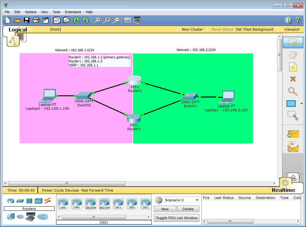
Packet Tracer 6.0.1 - HSRP topology example with Cisco 2901 ISR routers

Two network are configured for this tutorial :
  • Network 192.168.1.0/24
    • Router0 : 192.168.1.2 (GigabitEthernet 0/0)
    • Router1 : 192.168.1.3 (GigabitEthernet 0/0)

  • Network 192.168.2.0/24
    • Router0 : 192.168.2.2 (GigabitEthernet 0/1)
    • Router1 : 192.168.2.3 (GigabitEthernet 0/1)
Two HSRP groups are configured on the ISR routers :
  • HSRP Group 1 :
    • IP address : 192.168.1.1
    • Router0 with priority 120 (preemption enabled)
    • Router1 with HSRP default priority (100)

  • HSRP Group 2 :
    • IP address : 192.168.2.1
    • Router0 with priority 120 (preemption enabled)
    • Router1 with HSRP default priority (100)

Routers configuration

Router0 configurationRouter1 configuration
interface GigabitEthernet0/0
 ip address 192.168.1.2 255.255.255.0
 duplex auto
 speed auto
 standby version 2
 standby 1 ip 192.168.1.1
 standby 1 priority 120
 standby 1 preempt
!
interface GigabitEthernet0/1
 ip address 192.168.2.2 255.255.255.0
 duplex auto
 speed auto
 standby version 2
 standby 2 ip 192.168.2.1
 standby 2 priority 120
 standby 2 preempt
interface GigabitEthernet0/0
 ip address 192.168.1.3 255.255.255.0
 duplex auto
 speed auto
 standby version 2
 standby 1 ip 192.168.1.1
!
interface GigabitEthernet0/1
 ip address 192.168.2.3 255.255.255.0
 duplex auto
 speed auto
 standby version 2
 standby 2 ip 192.168.2.1

Preemption is configured on Router0 using the standby X preempt commands. This router will always assume HSRP active state when it's online and if it has the highest HSRP priority in the network. The same configuration without the standby x priority 120 configuration on Router0 does not work and Router1 assumes the active state because it has a higher IP address configured.

Testing the configuration

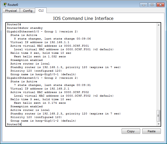
Packet Tracer 6.0 - HSRP active router (ISR 2911) with preemption enabled

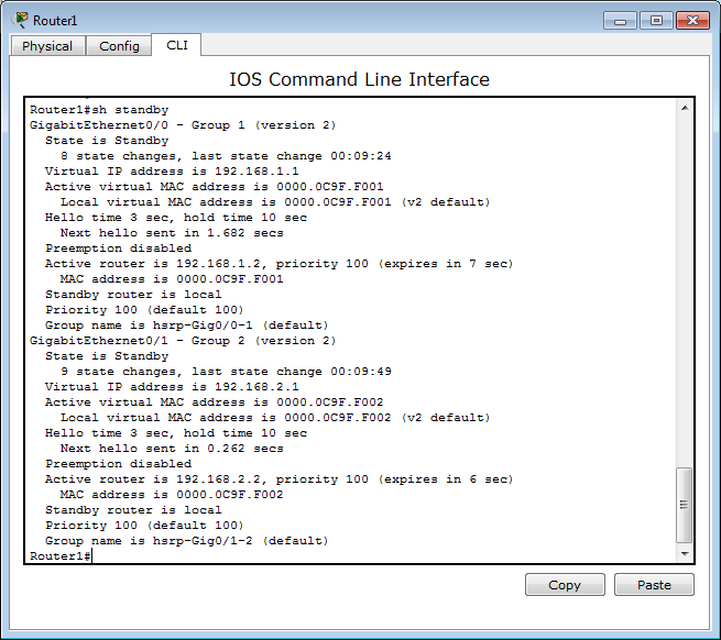
Packet Tracer 6.0 - HSRP standby router (ISR 2911) with 2 groups

Router0 is active for both HSRP groups. Both routers detected each other correctly but the priority seems to be wrong (Standby router is 192.168.1.3, priority 120 should be Standby router is 192.168.1.3, priority 100 on Router0)

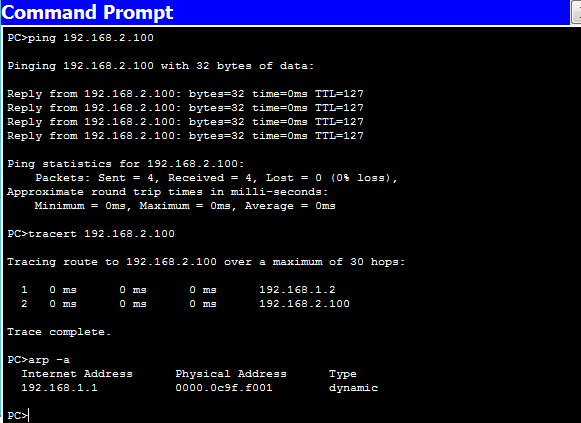
Testing HSRP configuration is Packet Tracer 6.0.1 (ping, tracert, arp) 

Ping, traceroute and arp commands issued on Laptop0 confirms that the configuration is working. The IP packets are transiting through Router0 (192.168.1.2)

Known bug

HSRP can be configured the same way on Cisco 3750 multilayer switch vlan interfaces in Packet Tracer 6.0.1.

interface Vlan100
 ip address 192.168.1.2 255.255.255.0
 standby version 2
 standby 1 ip 192.168.1.1
 standby 1 preempt
!
interface Vlan200
 ip address 192.168.2.2 255.255.255.0
 standby version 2
 standby 2 ip 192.168.2.1
 standby 2 preempt

However :
  • Laptops can't ping the HSRP IP addresses configured on the multilayer switches
  • The packets are not forwarded between the 2 laptops if the HSRP address are the default gateways configured on both pc.

Cisco paket tracer 6 latest


Cisco Packet Tracer v6.0. 1


Cisco Packet tracer is a powerful network simulation tools, which helps a network engineer to design a network virtually. Recently updated their version. The previous version was 5.3.3. That version didn’t support IP v 6, but this version support IP v 6. Also some other essential elements you can get easily. This is really awesome. Hope that you can enjoy with it.
Here I’m providing download link of Cisco Packet Tracer 6.0.1 for windows.


Download  (no tutorials)


  Download (with tutorials)